The SCADuino Primo – a proof-of-concept SCADBoard
By: J. Pagliaccio and B. Reidy March 2014
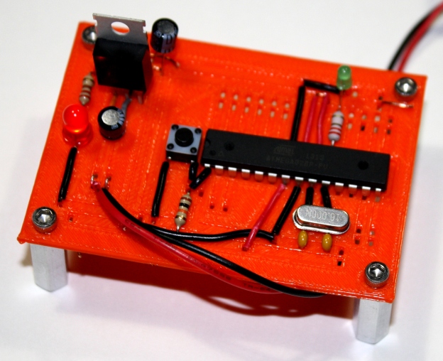
3D Printed Breadboard Arduino
SCADuino is a 3D printable version of the Breadboard Arduino at Arduino.cc. Using OpenSCAD and the SCADBoard library it is easy to create a 3D printable breadboard like the Breadboard Arduino.

SCADuino created using SCADBoard
The design for the Breadboard Arduino can be found at the Arduino website here: http://arduino.cc/en/Main/Standalone The Arduino site has a step-by-step instruction for assembling the boards plus a bill of materials – the necessary components. All of the components are easy to find on https://www.sparkfun.com/ and https://www.adafruit.com/. We built the Breadboard Arduino first and used it as a reference to build our SCADuino. We also recommend using an Arduino Uno R3 like this https://www.adafruit.com/products/50 for programming the SCADuino. We program and then pop out the Atmega328 and put it in the SCADuino.
The SCADuino Code
We developed two versions of the SCADuino; one with normal size thru holes and one with oversized thru-holes that will fit 2 wires in each hole. Both versions are included in the SCAD file. The code is straight forward with comments in the code. The pictures represent the 2-wire version. Please note the SCADBoard library is at http://scadboard.wordpress.com/.
/*
  SCADBoard Library & SCADuino
  -------------------------------------------
  3D Printable Breadboard Library in OpenSCAD.

  File: SCADuino_0_0_13.scad

  Copyright (c) 2014,  J. Pagliaccio, B. Reidy. All rights reserved.

  Redistribution and use in source and binary forms, with or without
  modification, are permitted provided that the following conditions are met:

   * Redistributions of source code must retain the above copyright notice,
     this list of conditions and the following disclaimer.

  THIS SOFTWARE IS PROVIDED BY THE COPYRIGHT HOLDERS AND CONTRIBUTORS
  "AS IS" AND ANY EXPRESS OR IMPLIED WARRANTIES, INCLUDING, BUT NOT
  LIMITED TO, THE IMPLIED WARRANTIES OF MERCHANTABILITY AND FITNESS FOR
  A PARTICULAR PURPOSE ARE DISCLAIMED. IN NO EVENT SHALL THE COPYRIGHT
  OWNER OR CONTRIBUTORS BE LIABLE FOR ANY DIRECT, INDIRECT, INCIDENTAL,
  SPECIAL, EXEMPLARY, OR CONSEQUENTIAL DAMAGES (INCLUDING, BUT NOT LIMITED
  TO, PROCUREMENT OF SUBSTITUTE GOODS OR SERVICES; LOSS OF USE, DATA, OR
  PROFITS; OR BUSINESS INTERRUPTION) HOWEVER CAUSED AND ON ANY THEORY OF
  LIABILITY, WHETHER IN CONTRACT, STRICT LIABILITY, OR TORT (INCLUDING
  NEGLIGENCE OR OTHERWISE) ARISING IN ANY WAY OUT OF THE USE OF THIS
  SOFTWARE, EVEN IF ADVISED OF THE POSSIBILITY OF SUCH DAMAGE.

  By: J. Pagliaccio, B. Reidy

  Version History
  -------------------------------
  v0.0.1 First printed prototype.
  v0.0.2 Wider center line fix.
  v0.0.3 Added ic module.
  v0.0.4 Underwire.
  v0.0.5 LED Module.
  v0.0.6 Better base and cleanup.
  v0.0.7 Parameters for all values.
  v0.0.9 Separate x and y values for each hole for 2-wires-in-a-hole.
  v0.0.10 SCADuino with 2-wire.
  v0.0.11 SCADuino with 2-wire April 2014.
  v0.0.12 SCADuino with 2-wire cleanup 1/2 deep May 2014.
  v0.0.13 Added license and library file.

*/

// Start of required variables

drillHoleRad = 2;
holeDiam = 1.25; // the tru-hole diameter in mm
holeLenX = holeDiam;
holeLenY = holeDiam;

// if two Wires in One Hole
holeLenY = holeDiam + .9;

holeSpace=2.54; // The hole spacing in mm
//Note: .1 inch = .0254 centimeters

// Thickness of the board
materialThick = 1.5; //2.54; // for prod - measured in mm

// Depth of the troughs
inset = materialThick *.5;
deepInset = materialThick *.5;

// End of required variables

include <SCADBoard_Lib_0_0_13.scad>

/*

Specify breadboards locations using standard breadboard
nomenclature of rows and columns, as follows:

•	Specify rows as numbers 1,2,3..
•	Specify columns with lower case letters like a standard breadboard a, b, c …
•	Valid columns are blp, bln, a, b, c, d, e, 8, 9, f, g, h, i, j, brp, brn.
•	blp, bln stand for bus left negative, bus left positive
•	brp, brn stand for bus right positive, bus right negative.
•	Columns 8 and 9 are valid columns.

*/

// Call the module
// SCADuino1Wire();
SCADuino2Wire();

//----------------------------------------------------------------------------
// 1-wire SCAD + Arduino = SCADUINO
//----------------------------------------------------------------------------
module SCADuino1Wire(){

  difference() {
  //union() {

	union()
	{
		createboard(25, "YellowGreen");
	}
	union()
	{

		// blp bln A B C D E  8 9  F G H I J brp brn
		//------------------------------------------

		//--- Start of busses
		// long left vert side buses
		wire(1,bln,22,bln, neg);
		wire(2,blp,22,blp, pos);

		// long right vert side busses
		wire(2,brn,23,brn, neg);
		wire(1,brp,23,brp, pos);

		// cross board bus to bus
		wire(6,blp,6,brp, pos);
	   wire(7,bln,7,brn, neg);

		hole(10,blp,thru); // extra bus holes
		//--- End of busses

		wire(1,bln,1,e, neg); // Neg left trace to LED
		led(1,e+1, 1,e+2, yellowled); // LED
		wire(1,f, 1,i, pos); // LED Pos
		wire(1,j, 1,brp, resistor); // Resistor

		wire(3,c,3,h, pos); // Cap Pos
		wire(4,c,4,h, neg); // LED Resistor

		hole(3,b,thru); // Power in
		hole(4,b,thru); // Power in

		hole(3,9,thru); // Cap
		hole(4,9,thru); // Cap

		hole(3,h,thru); // 5V Regulator
		hole(4,h,thru); // 5V Regulator
		hole(5,h,thru); // 5V Regulator

		wire(4,h,4,brn, neg); // Power Bus Neg Right
		wire(5,h,5,brp, pos); // Power

		// Power Cap
		hole(6,brp,thru);
		hole(5,brn,thru);

		// Reset Push Button
		pushbutton(8,e,10,f,"Silver");

		wire(8,e,8,bln, neg); // Button
		wire(10,c,10,d, neg); // Button
		wire(10,c,11,c, neg); // Button

		wire(11,blp,11,e, resistor); // Power Bus Neg Right

		// blp bln A B C D E  8 9  F G H I J brp brn
		//------------------------------------------

		// TX and RX
		wire(12,b,12,e, resistor);
		wire(13,b,13,e, resistor);

		// ATMEL Processor
		ic(11,e,25,f,neg);

		// Analog Pins
		for(n=[11:1:16])
		{
			hole(n,j,thru);
			wire(n,f,n,i, trace);
		}

		// Left Side
		wire(15,blp,17,e, pos); // ATMEL Mid power 7
		wire(17,bln,18,e, neg); // ATMEL Mid ground 8

		// Little cap 1 and Crystal
		wire(19,bln,19,a, cap);
		hole(19,b,thru);
		wire(19,c,19,e, neg);

		// Little cap 2 and Crystal
		wire(21,bln,21,a, cap);
		hole(20,d,thru);
		wire(21,c,20,d, neg);
		wire(20,d,20,f, neg);
		wire(21,c,21,bln, neg);

		// Right side
		wire(17,f,17,brn, neg); // ATMEL 22
		wire(18,f,18,brp, pos); // ATMEL 21
		wire(19,f,19,brp, pos); // ATMEL 20

		// LED pin 13 to ground
		wire(20,f,20,i, led);
		wire(20,j,20,brn, neg);

		// Piezo pin 13 to ground
		wire(21,f,21,i, led);
		wire(21,j,21,brn, neg);

		// ATMEL Analog Pins
		for(n=[23:1:24])
		{
			// Left Side
			hole(n,a,thru);
			wire(n,b,n,e, led);
		}
		// ATMEL Analog Pins
		for(n=[22:1:24])
		{
			// Right Side
			hole(n,j,thru);
			wire(n,f,n,i, led);
		}

	 }
  }
}

//----------------------------------------------------------------------------
// SCADuino with 2 wires per hole for easy assembly
//----------------------------------------------------------------------------
module SCADuino2Wire(){

  difference() {
  //union() {

	union()
	{
		createboard(25, "YellowGreen");
	}
	union()
	{
		// blp bln A B C D E  8 9  F G H I J brp brn
		//------------------------------------------

		//--- Start of busses
		// long left vert side buses
		wire(1,bln,17,bln, neg);
		wire(2,blp,15,blp, pos);

		// long right vert side busses
		wire(2,brn,23,brn, neg);
		wire(1,brp,23,brp, pos);

		// cross board bus to bus
		wire(6,blp,6,brp, pos);
	   wire(7,bln,7,brn, neg);

		hole(10,blp,thru); // extra bus holes

		// Left side bus jogggle for caps
		wire(17,blp,22,blp, neg);

		//--- End of busses

		// Top LED section
		wire(1,bln,1,8, neg); // Neg left leed to LED
		led(1,8,1,9, yellowled); // LED
		wire(1,9,1,brp, resistor); // Resistor

		// Start of power section
		hole(3,b,thru); // Power in holes
		hole(4,b,thru); // Power in holes

		wire(3,c,3,h, pos); // Power pos wire to regulator
		wire(4,c,4,h, neg); // Power neg wire to regulator

		hole(3,f, cap); // Cap pos
		hole(4,f, cap); // Cap neg

		hole(3,h,pos); // 5V Regulator
		hole(4,h,neg); // 5V Regulator
		hole(5,h,pos); // 5V Regulator

		wire(4,h,4,brn, neg); // Power Bus Neg Right
		wire(5,h,5,brp, pos); // Power

		// Power Cap
		hole(2,brp,cap);
		hole(2,brn,cap);
		hole(3,brp,cap); // extra hole
		hole(3,brn,cap); // extra hole

		// End of power section

		// Reset Push Button
		pushbutton(8,e,10,f,"Silver");

		wire(8,bln,8,e, neg); // button Neg
		wire(10,c,10,e, pos); // button Pos
		wire(10,c,11,c, pos); // Button pos to pin 1

		// blp bln A B C D E 8 9 F G H I J brp brn
		//------------------------------------------

		// ATMEL ATmega328 Processor
		ic(11,e,25,f,neg);

		wire(11,blp,11,e, pos); // Power Bus Neg Right

		// TX and RX
		wire(12,b,12,e, resistor);
		wire(13,b,13,e, resistor);

		// ATMEL Analog Pins 0-5 Right
		for(n=[11:1:16])
		{
			hole(n,i,thru);
			wire(n,f,n,j, trace);
		}

		// Left Side mid side power and ground
		wire(15,blp,17,e, pos); // ATMEL Power 7 mid
		wire(17,bln,18,e, neg); // ATMEL Power 8 mid

		// Left Little cap 1 and Crystal
		wire(19,blp,19,b, cap); // to the joggle
		hole(19,bln,cap); // to the joggle
		wire(19,b,19,e, neg);

		// Little cap 2 and Crystal
		wire(21,blp,21,b, cap); // to the joggle
		hole(21,bln,cap); // to the joggle
		wire(21,b,20,e, neg);

		// Right side
		wire(17,f,17,brn, neg); // ATMEL
		wire(18,f,18,brp, pos); // ATMEL
		wire(19,f,19,brp, pos); // ATMEL

		// LED pin 13 to ground
		wire(20,f,20,i, led);
		wire(20,j,20,brn, neg);

		// Piezo pin 13 to ground
		wire(21,f,21,i, led);
		wire(21,j,21,brn, neg);

		//underwire(9,bln,17,bln, neg);

		wire(18,brn,19,brn, neg);

		// blp bln A B C D E 8 9 F G H I J brp brn
		//------------------------------------------

		// ATMEL Pins Left
		for(n=[23:1:24])
		{
			// Left Side
			hole(n,a,thru);
			wire(n,b,n,e, led);
		}

		// ATMEL Pins Right
		for(n=[22:1:24])
		{
			// Right Side
			hole(n,h,thru);
			wire(n,f,n,j, led);
		}
	 }
  }
}
The source file is: SCADuino_0_0_13.scad
The include library file is: SCADBoard_Lib_0_0_13.scad
The printable STL file is: SCADuino_0_0_13.stl

SCADuino being printed using MakerWare
http://scadboard.wordpress.com/
BOM – the Bill of materials to build a board
- (1) Atmega328P with Arduino bootloader – like this https://www.adafruit.com/product/123
- (1) 7805 5V Voltage regulator
- (2) LEDs
- (2) 220 Ohm resistors
- (1) 10k Ohm resistor
- (2) 10 uF capacitors
- (1)16 MHz clock crystal
- (2) 22 pF capacitors
- (1) Momentary normally open (“off”) button
- And Red and Black 22 AWG wire
Software Used
- OpenSCAD http://www.openscad.org/
- Arduino http://arduino.cc/
- MakerWare http://makerbot.com/
- Blender http://www.blender.org/
- Fritzing http://fritzing.org/
- Inkscape http://www.inkscape.org/
SCADBoard and SCADuino source code is available at http://scadboard.wordpress.com/
Thank you to:
- OpenSCAD for their software.
- Arduino for all their inspirational microcontroller designs.
- Adafruit and Sparkfun for being reliable sources of electronics microcontroller components and all of the Adafruit tutorials.
- Mr.Hoppner and the LVCSD for supporting our various projects.
Special thanks to our friends at Bladykas & Panetta for the generous donation of computers for this project. They are Engineers and Land Surveyors at http://www.panettasurveying.com
All product and service names mentioned are the trademarks of their respective companies. Copyright (c) 2014, J. Pagliaccio, B. Reidy. All rights reserved.
Redistribution and use in source and binary forms, with or without modification, are permitted provided that the following conditions are met: Redistributions of source code must retain the above copyright notice, this condition and the following disclaimer.
THIS SOFTWARE IS PROVIDED BY THE COPYRIGHT HOLDERS AND CONTRIBUTORS “AS IS” AND ANY EXPRESS OR IMPLIED WARRANTIES, INCLUDING, BUT NOT LIMITED TO, THE IMPLIED WARRANTIES OF MERCHANTABILITY AND FITNESS FOR A PARTICULAR PURPOSE ARE DISCLAIMED. IN NO EVENT SHALL THE COPYRIGHT OWNER OR CONTRIBUTORS BE LIABLE FOR ANY DIRECT, INDIRECT, INCIDENTAL, SPECIAL, EXEMPLARY, OR CONSEQUENTIAL DAMAGES (INCLUDING, BUT NOT LIMITED TO, PROCUREMENT OF SUBSTITUTE GOODS OR SERVICES; LOSS OF USE, DATA, OR PROFITS; OR BUSINESS INTERRUPTION) HOWEVER CAUSED AND ON ANY THEORY OF LIABILITY, WHETHER IN CONTRACT, STRICT LIABILITY, OR TORT (INCLUDING NEGLIGENCE OR OTHERWISE) ARISING IN ANY WAY OUT OF THE USE OF THIS SOFTWARE, EVEN IF ADVISED OF THE POSSIBILITY OF SUCH DAMAGE.
Julian Pagliaccio and Brian Reidy
